The Problem
The most complex and the least understood aeroelasticity phenomena occur in multi-stage core compressors because of their wide operating envelope. During engine development programmes, very costly structural failures are known to occur because of a mixture of aeroelastic instabilities such as acoustic resonances, rotating stall, surge, flutter, blade-passing and low engine-order forced response, buffeting, etc.
The Challenge
The numerical modelling of core-compressor aeroelasticity is a formidable challenge as the analysis must be able to represent accurately not only the aerodynamic and structural properties of a large number of bladerows but also the interactions through these. Two fundamental difficulties can be identified from the outset. First, the close spacing of the bladerows compromises the accuracy of single-bladerow analyses, but multi-bladerow studies yield very large models and may require prohibitively large amounts of CPU time for time-accurate viscous unsteady flow representations. Second, the model must be able to deal with a vast range of time and length scales of the flow. For instance, the time scale can be determined by the axial propagation of the low-frequency acoustic waves, or by the blade vibratory motion at several times the blade-passing frequency. Similarly, the length scale can be the circumference/axial length of the machine, or the blade boundary layer thickness.
Use of HPCx
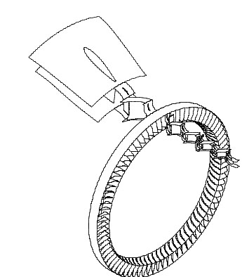
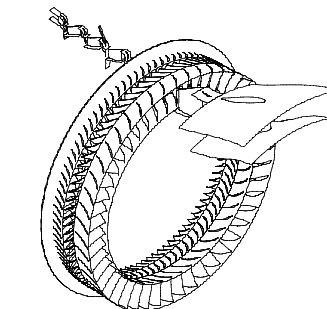
Although flutter analyses with time-linearised unsteady flow models are possible, here we will consider time domain analyses only. The simplest time-domain analysis is based on single-passage representation of the blade, with phase-lagged boundary conditions at the periodic boundaries to represent a chosen inter-blade phase angle (IBPA). The blade is forced to vibrate at a given frequency and amplitude, the aero-damping being computed from energy considerations. A more advanced, albeit more expensive, approach is to model the whole bladerow of interest which also allows the inclusion of all modes of vibration. The system is given an initial perturbation and the aero-damping is evaluated from the decay (or growth) of the modal amplitude of each mode. Compared to the single-passage approach, the analysis is more general because there is no need to assume a certain vibration pattern. The whole-annulus model can be extended to several bladerows in order to include their effect on flutter stability. Such an approach, though needed when dealing with closely-spaced bladerows, can become prohibitively expensive. A alternative is to use a hybrid single-passage whole-annulus model where the bladerows of interest are represented in full while those further away are included as single passages. The interblade-row boundaries between single-passage bladerows are represented using mixing planes, whilst boundaries between whole annulus bladerows are represented as sliding planes, thus allowing the representation of the unsteady interaction between the bladerows.
| Domains for forced response analysis |
| Domain |
No of bladerows |
Passages |
Size (Mpoints) |
Configuration |
| D |
1 |
1 |
2.65 |
SP rotor blade |
| E |
1 |
64 |
19 |
Whole-annulus NGV |
| F |
2 |
43/64 |
36 |
Whole-annulus NGV+rotor |
| Computational parameters for forced response analysis |
| Domain |
CPUs |
Partition |
CPU Hour |
Memory (Mb/CPU) |
| D |
32 |
Geometric |
144 |
65 (20% halo) |
| E |
256 |
MeTis |
4,608 |
50 (18% halo) |
| F |
512 |
MeTis |
9,216 |
40 (16% halo) |
Outcome
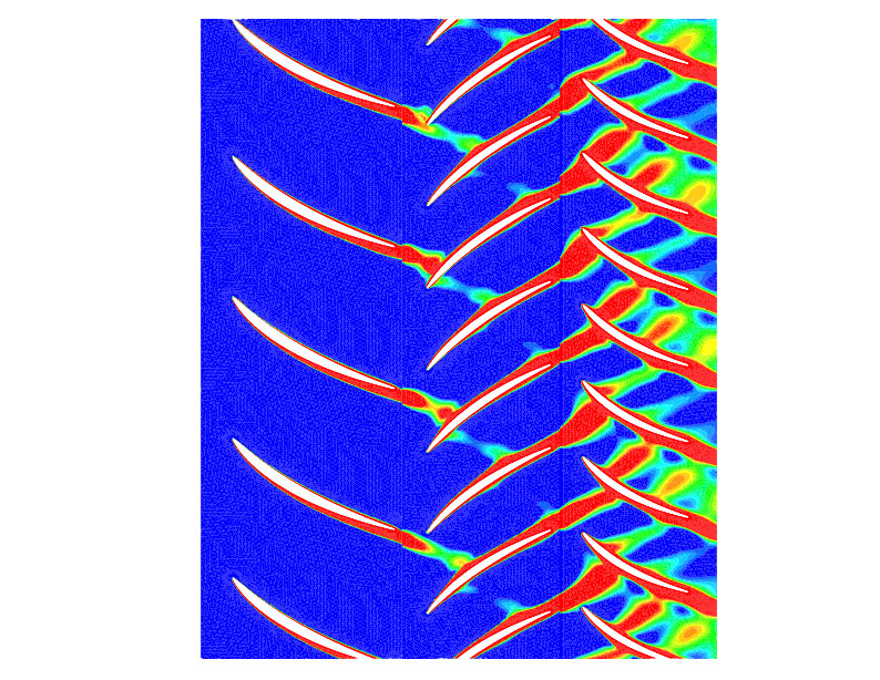
A marked difference was seen between single-bladerow and multi-bladerow computations. The former, irrespective of whether a single-passage or whole-annulus configuration is used, predicts a damping value of about 2% while the corresponding value is approximately halved for the latter. The discrepancy is due to the fact that unsteady bladerow interactions between the neighbouring blade-rows are ignored when using simpler domains.
Interactions between the neighbouring bladerows, lead to significantly different aerodynamic values depending on the modelling detail. Of particular interest are the upstream and downstream wakes which can be evaluated by monitoring the modal force on a particular bladerow. The forces were decomposed in forward and backward travelling wave components. For the 35 and 9 engine-order excitations the forcing from S2 is aliased to a forward travelling wave because of blade count. In addition, the 26 and 39 engine-order forcing represent three-way interactions with R2 on one hand, and with S1 and S2 on the other. The 26 engine-order spectrum shows a moderate peak at 250,000 rad/s, which is the main blade-passing frequency for this engine order. However, the response is higher at 350,000 rad/s. This is due to the waves from R2 being scattered and reflected by the blades of the neighbouring stators. A similar situation, but less pronounced, is visible in the 39 engine-order spectra.
Future:
The development of rotating stall, and surge, is being undertaken under EP/F001789/1.
References:
- Vahdati, M., Sayma, A. I., Simpson, G. and Imregun, M. Multibladerow Forced Response Modeling in Axial-Flow Core Compressors, ASME Journal of Turbomachinery, 129(2) 412-420, April 2007
|